Wire as defined by "Compton’s Encyclopedia" is a strand of metal in the form of a flexible thread or slender rod. This is the most common form of conductors for power transmission, smaller electrical signals, or as resistors. Insulated wires are most often used in electronic circuits. The insulation provides electrical insulation and mechanical and chemical protection.
Different Types of Connecting Wires
Wires are either solid or stranded. Most wires are round, occasionally square or rectangular conductors are used, such as integrated circuit external leads. Metals usually used in making wires are aluminum, alloy and copper. Insulation is made up of rubber or non-conductive materials and can come in different sizes and colors.
- Solid Wires
These wires are single solid wires with rubber insulation. Usually used in connecting circuits or wiring connections in a protoboard.
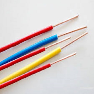
Photo source
- Stranded Wires
Is a group of wires used as a single wire. Due to their high flexibility, stranded wires are the most commonly used conductors. There is no sharp distinction between stranded wire and cable wires. Stranded constructions vary in the size, number and configuration of the individual strands. All stranded designation systems relate to the total cross-sectional area of the conductor. The cross-sectional area of metal determines the electrical resistance and current carrying capacity of the conductor and is important for the proper size selection for a specific application.
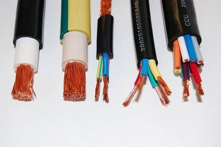
Photo source
Uses of Wires
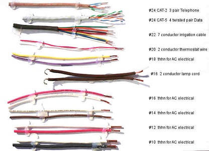
Photo source
The making of wire is one of man’s most useful industries. Through it’s manufacture, living standards have been greatly improved. Without wires many of the important inventions of modern times might never have been developed. Wire is a vital part of daily living and in communications. The telegraph and the telephone, streetcars and trolley buses get their power from the heavily changed wires overhead. Electric lights in the home, in public buildings and on the streets are changed in the power transmitted over steel and copper wire.
The mainspring mechanism of a watch is made of the finest tempered and flattened wire. Protective fences around the homes or country fields are often made of woven steel wire. Suspension bridges and bicycles contain it in their spokes and springs. Inside the instrument, satellites orbiting in the outer space could not transmit information back to ground tracking stations.
History of Wire Making
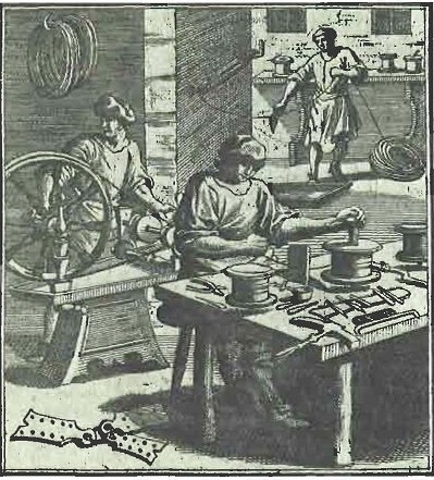
Photo source
Wire has been in use for many hundreds of years. It was known in Nineveh and Egypt in 800 B.C. It was made then and for many centuries afterwards by beating metal into plates. These were then cut into strips and rounded by further beating. Wire drawing was known in the 14th century, but the machinery used in this process and the Bessemer steel process were not perfected until the 19th century.
In modern wire plants, the raw materials, usually steel, is received in the form of small bars, or bullets. The bullets are heated and conveyed to a set of rolls to be reduced in size. Finally, for ordinary sizes of wire, each bullet is rolled down to a rod smaller than a lead pencil. The heated rod is carried through a pipe to a device which coils the rod. The coiled metal is cooled and taken to the plant where it is drawn into wire of all sizes.
First the scale, which has accumulated, is removed by an acid bath, and the acid in turn is removed in an alkali bath. Next, the rod with a small, sharp point enters a bell-mouthed hole in a draw plate, or die, made of hard steel or in some cases of a diamond or ruby. It emerges from the smaller end of the hole reduced in size. The process of drawing the wire through smaller and smaller holes continues until the desired size is reached. As the metal is drawn finer it becomes harder and more brittle. This from time to time the metal must be annealed to make it soft and tough, and it must be constantly oiled as it is pulled through the dies, or perforated plates.
Wire Gauges
Wire gauges as described in Electronics Engineer’s Handbook by Donald Fink is used to assist manufacturers in the production of wire of standard dimensions and weights, several standard wire sizes, or gauges, have been established in the industry.
- AWG (American B & S).
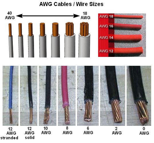
Photo source
This wire gauge divides the range from 0.0050 in. (AWG No.36) to 0.4600 in. (AWG No.0000) into 39 intervals. Sizes progress in geometrical fashion with a ratio of 1.229322 between adjacent gauges. The American Wire Gauge, previously known as the Brown & Sharpe (B&S) Gauge, is the standard designation for copper wire sizes in the United States. It was originally designed to standardize wire drawing and solid wire sizes in a mathematical progression. AWG is based on two reference diameters, 0.4600 inches (4/0 AWG) and 0.0050 inches (36 AWG). All gauge sizes are related to each other in a mathematical progression such that each size can be derived from any known AWG size and diameter (refer to ASTM B 258 for specific details).
An increase of one AWG number signifies a 20.7% reduction in cross-sectional area and a 26.1% increase in length. A 3 AWG change doubles or halves the cross-sectional area and a 6 AWG change doubles or halves the diameter. For sizes smaller than 36 AWG, diameters are extrapolated using the same relationship. AWG sizes are also used to describe the size of a stranded conductor.
- BWG (Birmingham Wire Gauge).
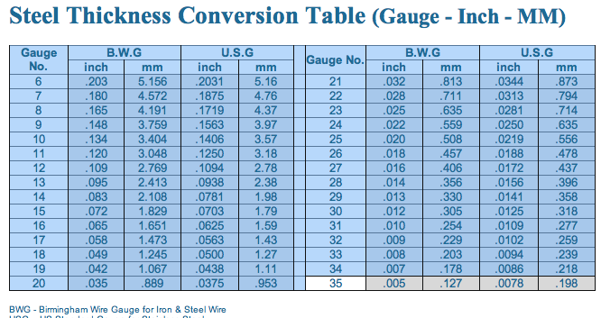
Photo source
An English based on the number of drawings necessary to produce the wire. SWG ( British Standard Wire Gauge).The legal standard in Great Britain similar to BWG. Metric Wire Gauge. 0.1mm is No.1, 0.2mm is No.2, etc. Steel Wire Gauge. Used exclusively for steel wire. A direct way to specify wire size is to give the diameter in mils (1 mil=0.001 in.)
Sources
Compton’s Encyclopedia vol. 64. (1967). Wire. U.S.A: F.E. Compton Company
Fink, Donald G. (1975). Electronics Engineer’s Handbook. Quezon City, Philippines: JMC Press, Inc.
Fink, Donald G. and Donald Christiansen (1986). Electronics Engineer’s Handbook. 2nd Ed. Singapore: McGraw-hill Inc.
Fink, Donald G. and H. Wayne Beaty (1993). Standard Handbook for Electrical Engineers. Singapore: McGraw-Hill Inc.
No comments:
Post a Comment